Buttweld Short Stub End Weight Chart: A Complete Product Guide
February 12, 2026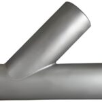
Buttweld Lateral Tee Weight Chart – Dimensions, Specifications & Industrial Applications
February 13, 2026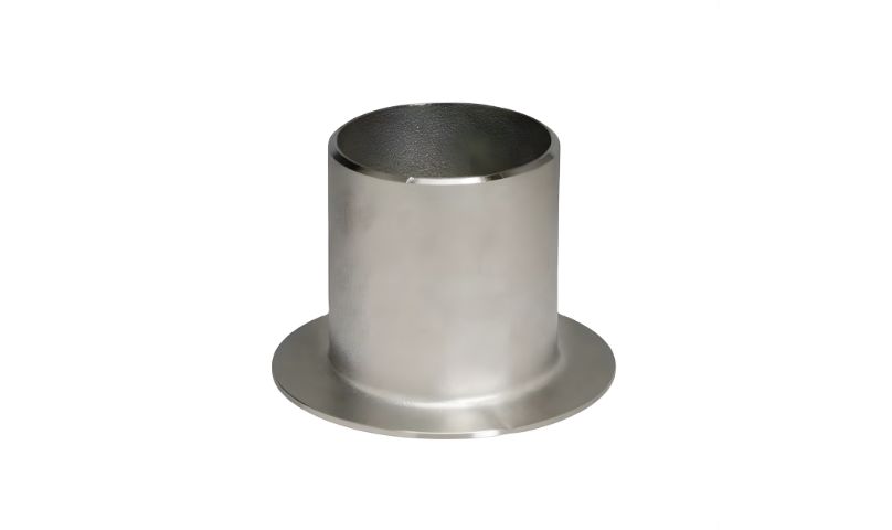
In the field of industrial piping, the requirements of accuracy and compatibility are of utmost importance. One of the piping fitting requirements in industries such as oil & gas, petrochemical, power, or water is the Buttweld Long Stub End fitting. To make proper plans, engineers and customers use the Buttweld Long Stub End Weight Chart.
This blog explains what a buttweld long stub end is, why weight charts matter, and how to use them effectively.
What Is a Buttweld Long Stub End?
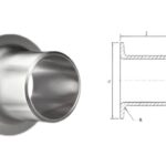
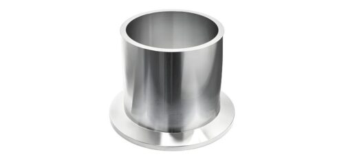
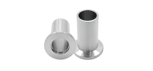
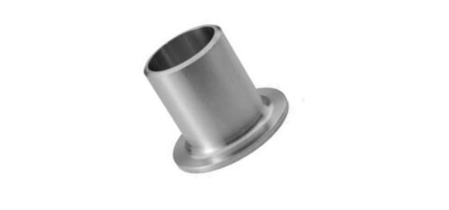
A Buttweld Long Stub End is a pipe fitting meant for use with a lap joint Flange in a pipeline system. It is designed to have a longer neck as compared to a short stub end to allow for better welding. In a long stub end, the pipe is welded to the stub end, while the lap joint flange is free to rotate.
Buttweld long stub ends are generally available in accordance with the ASME B16.9 Specification. This buttweld long stub end is widely used in those situations or industries that require frequent maintenance, inspection, or adjustment. This component has a smooth bore that provides an uninterrupted flow of fluid.
Key Features:
- Long neck design for improved welding strength
- Compatible with lap joint flanges
- Smooth bore for efficient fluid flow
- Available in various materials and standards
These fittings are commonly manufactured according to ASME B16.9 standards.
| NPS | Y (Outside Diameter) | T (Wall Thickness) | 45° LR Elbow Centre to Face B | 45° LR Elbow Weight | 90° LR Elbow Centre to Face A | 90° LR Elbow Weight | 90° SR Elbow Centre to Face A | 90° SR Elbow Weight | ||
| mm | in | mm | mm | Schedule | mm | kg | mm | kg | mm | kg |
| 15 | 1/2” | 21.3 | 2.78 | STD | 15.9 | 0.04 | 38.1 | 0.08 | – | – |
| 3.73 | X.S | 15.9 | 0.05 | 38.1 | 0.10 | – | – | |||
| 20 | 3/4” | 26.7 | 2.87 | STD | 11.1 | 0.04 | 28.6 | 0.08 | – | – |
| 3.91 | X.S | 11.1 | 0.05 | 28.6 | 0.11 | – | – | |||
| 25 | 1” | 33.4 | 3.38 | STD | 22.2 | 0.09 | 38.1 | 0.15 | 25.4 | 0.11 |
| 4.55 | X.S | 22.2 | 0.11 | 38.1 | 0.19 | 25.4 | 0.14 | |||
| 32 | 11/4” | 42.2 | 3.56 | STD | 25.4 | 0.14 | 47.6 | 0.28 | 31.75 | 0.18 |
| 4.85 | X.S | 25.4 | 0.2 | 47.6 | 0.39 | 31.75 | 0.24 | |||
| 40 | 11/2” | 48.3 | 3.68 | STD | 28.6 | 0.2 | 57.1 | 0.4 | 38.1 | 0.26 |
| 5.08 | X.S | 28.6 | 0.25 | 57.1 | 0.5 | 38.1 | 0.35 | |||
| 50 | 2” | 60.3 | 3.91 | STD | 34.9 | 0.36 | 76.2 | 0.72 | 50.8 | 0.5 |
| 5.54 | X.S | 34.9 | 0.5 | 76.2 | 1.0 | 50.8 | 0.68 | |||
| 65 | 21/2” | 73.0 | 5.16 | STD | 44.4 | 0.73 | 95.2 | 1.46 | 63.5 | 0.95 |
| 7.01 | X.S | 44.4 | 0.91 | 95.2 | 1.82 | 63.5 | 1.27 | |||
| 80 | 3” | 88.9 | 5.49 | STD | 50.8 | 1.1 | 114.3 | 2.18 | 76.2 | 1.45 |
| 7.62 | X.S | 50.8 | 1.45 | 114.3 | 2.86 | 76.2 | 1.95 | |||
| 100 | 4” | 114.3 | 6.02 | STD | 63.5 | 2.1 | 152.4 | 4.2 | 101.6 | 2.8 |
| 8.56 | X.S | 63.5 | 2.9 | 152.4 | 5.7 | 101.6 | 3.9 | |||
| 125 | 5” | 141.3 | 6.65 | STD | 79.4 | 3.4 | 190.0 | 6.8 | 127.0 | 4.8 |
| 9.5 | X.S | 79.4 | 5.0 | 190.0 | 10.0 | 127.0 | 6.5 | |||
| 150 | 6” | 168.3 | 7.11 | STD | 95.2 | 5.1 | 229.0 | 10.1 | 152.4 | 6.8 |
| 10.97 | X.S | 95.2 | 7.7 | 229.0 | 15.3 | 152.4 | 10.2 | |||
| 200 | 8” | 219.1 | 8.18 | STD | 127.0 | 10.2 | 305.0 | 20.4 | 203.0 | 13.6 |
| 12.7 | X.S | 127.0 | 15.5 | 305.0 | 30.9 | 203.0 | 20.9 | |||
| 250 | 10” | 273.9 | 9.27 | STD | 159.0 | 18.1 | 381.0 | 36.1 | 254.0 | 24.1 |
| 12.7 | X.S | 159.0 | 24.4 | 381.0 | 48.8 | 254.0 | 32.5 | |||
| 300 | 12” | 323.9 | 9.52 | STD | 190.0 | 26.6 | 457.0 | 53.1 | 305.0 | 35.4 |
| 12.7 | X.S | 190.0 | 35.0 | 457.0 | 70.0 | 305.0 | 46.7 | |||
| 350 | 14” | 355.6 | 9.52 | STD | 222.0 | 34.1 | 533.0 | 68.1 | 356.0 | 45.4 |
| 12.7 | X.S | 222.0 | 45.0 | 533.0 | 90.0 | 356.0 | 60.0 | |||
| 400 | 16” | 406.4 | 9.52 | STD | 254.0 | 45.0 | 610.0 | 89.3 | 406.0 | 59.5 |
| 12.7 | X.S | 254.0 | 59.0 | 610.0 | 118.0 | 406.0 | 78.7 | |||
| 450 | 18” | 457.0 | 9.52 | STD | 286.0 | 56.5 | 686.0 | 113.0 | 457.0 | 75.6 |
| 12.7 | X.S | 286.0 | 75.0 | 686.0 | 150.0 | 457.0 | 100.0 | |||
| 500 | 20” | 508.0 | 9.52 | STD | 318.0 | 85.0 | 762.0 | 140.0 | 508.0 | 93.5 |
| 12.7 | X.S | 318.0 | 112.5 | 762.0 | 186.0 | 508.0 | 124.0 | |||
| 600 | 24” | 610.00 | 9.52 | STD | 381.0 | 101.5 | 914.0 | 203.0 | 610.0 | 135.0 |
| 12.7 | X.S | 381.0 | 134.5 | 914.0 | 269.0 | 610.0 | 179.0 | |||
Why Is a Buttweld Long Stub End Weight Chart Important?
Apart from the general weight reference, the Buttweld Long Stub End Weight Chart is of immense importance to engineering accuracy and compliance with established requirements because it provides a very accurate weight reference that assists engineering professionals in assessing dead weight loads of respective pipes, especially those that traverse very long distances. It is also of particular value to procurement officers because it enables them to properly plan materials by ensuring that adequate and appropriate size fittings only are procured without any wastage that could attract additional costs. During installation, proper weight reference data is useful in the selection of installation tools, hence improving site safety. Additionally, the reference data is significant in export projects because it provides very useful weight charts for container loading and customs requirements.
A weight chart provides the exact weight of stub ends based on size, schedule, and material. This information is essential for:
- Accurate load and stress calculations
- Proper pipe support design
- Estimating transportation and handling costs
- Project budget planning
- Selecting the correct fitting for high-pressure applications
Without a reliable weight chart, incorrect assumptions can lead to design errors or increased project costs.
Standard Buttweld Long Stub End Weight Chart
| Nominal Pipe Size (NPS) | Outside Diameter (mm) | Length (mm) | Approx. Weight (kg) |
| 1/2″ | 21.34 | 76 | 0.5 |
| 1″ | 33.40 | 76 | 0.9 |
| 2″ | 60.33 | 89 | 2.1 |
| 3″ | 88.90 | 102 | 4.5 |
| 4″ | 114.30 | 102 | 6.8 |
| 6″ | 168.28 | 114 | 13.5 |
| 8″ | 219.08 | 127 | 25.0 |
| 10″ | 273.05 | 127 | 38.5 |
| 12″ | 323.85 | 140 | 55.0 |
Materials Available
Except for the use of regular carbon steel and stainless steel materials, the butt welding long stub ends can also be used to manufacture the fittings made of other specialized materials to withstand critical service conditions, such as elevated temperature, high pressure, etc. The surface finishes and heat treatments available, including solution annealing and normalizing, as well as pickling and passivation, also play a significant role in enhancing the properties of the materials used. This facilitates the process of selecting the appropriate material, which influences the weight, corrosion resistance, weldability, and overall life of the piping system, meeting the standards.
Buttweld long stub ends are available in a wide range of materials, including:
- Carbon Steel (ASTM A234 WPB)
- Stainless Steel (304, 304L, 316, 316L)
- Alloy Steel (WP11, WP22, WP91)
- Duplex & Super Duplex Steel
- Nickel Alloys (Inconel, Monel, Hastelloy)
Each material affects the overall weight and performance of the fitting.
Applications of Buttweld Long Stub Ends
Buttweld long stub ends are commonly used for modular piping installations, especially when easy assembly or disassembly is a requirement, as their design facilitates rapid alignment of these flanges. They are also commonly used for handling corrosive fluids, as it is easy to replace the lap joints without cutting the pipe. In industries like pharmaceuticals or food processing, buttweld long stub ends are commonly used for high-purity fluids to maintain maximum hygiene due to their smooth inside surfaces. Therefore, given their reliability, Buttweld long stub ends are commonly used for both onshore and offshore projects.
These fittings are widely used in:
- Oil & Gas pipelines
- Chemical and petrochemical plants
- Power generation systems
- Water treatment and desalination plants
- Food & pharmaceutical industries
Their ability to allow flange rotation makes them especially useful in complex piping layouts.
| Nominal Size (DN) | Nominal Size (NPS) | OD Max (mm) | OD Min (mm) | Long Type Length (F) | Short Type Length (F) | Radius A (R) | Radius B max (R) | Diameter of Lap (C) |
| 15 | 1/2 | 22.8 | 20.5 | 76 | 51 | 3 | 0.8 | 35 |
| 20 | 3/4 | 28.1 | 25.9 | 76 | 51 | 3 | 0.8 | 43 |
| 25 | 1 | 35.0 | 32.6 | 102 | 51 | 3 | 0.8 | 51 |
| 32 | 1 1/4 | 43.6 | 41.4 | 102 | 51 | 5 | 0.8 | 64 |
| 40 | 1 1/2 | 49.9 | 47.5 | 102 | 51 | 6 | 0.8 | 73 |
| 50 | 2 | 62.4 | 59.5 | 152 | 64 | 8 | 0.8 | 92 |
| 65 | 2 1/2 | 75.3 | 72.2 | 152 | 64 | 8 | 0.8 | 105 |
| 80 | 3 | 91.3 | 88.1 | 152 | 64 | 10 | 0.8 | 127 |
| 90 | 3 1/2 | 104.0 | 100.8 | 152 | 76 | 10 | 0.8 | 140 |
| 100 | 4 | 116.7 | 113.5 | 152 | 76 | 11 | 0.8 | 157 |
| 125 | 5 | 144.3 | 140.5 | 203 | 76 | 11 | 1.6 | 186 |
| 150 | 6 | 171.3 | 167.5 | 203 | 89 | 13 | 1.6 | 216 |
| 200 | 8 | 222.1 | 218.3 | 203 | 102 | 13 | 1.6 | 270 |
| 250 | 10 | 277.2 | 272.3 | 254 | 127 | 13 | 1.6 | 324 |
| 300 | 12 | 328.0 | 323.1 | 254 | 152 | 13 | 1.6 | 381 |
| 350 | 14 | 359.9 | 354.8 | 305 | 152 | 13 | 1.6 | 413 |
| 400 | 16 | 411.0 | 405.6 | 305 | 152 | 13 | 1.6 | 470 |
| 450 | 18 | 462.0 | 456.0 | 305 | 152 | 13 | 1.6 | 533 |
| 500 | 20 | 514.0 | 507.0 | 305 | 152 | 13 | 1.6 | 584 |
| 550 | 22 | 565.0 | 558.0 | 305 | 152 | 13 | 1.6 | 641 |
| 600 | 24 | 616.0 | 609.0 | 305 | 152 | 13 | 1.6 | 692 |
How to Use the Weight Chart Correctly
To obtain the most accurate level of precision, the weight chart should be cross-checked by approved drawings and material test certificates, as well as being in conformance to the proper standard, such as ASME B16.9, and also to the specific pipe schedule. Special alloys or any non-standard thicknesses are best obtained from the manufacturer for exact calculated weights rather than going for approximate values, as well as adding a buffer to the total piping weight calculations when involving large quantities. Proper application of the weight chart will help avoid installation issues, structural overloads, and even sudden project delays.
To select the correct stub end:
- Identify the Nominal Pipe Size (NPS)
- Confirm the schedule or wall thickness.
- Select the material grade.
- Refer to the weight chart for the exact weight.
- Verify compliance with ASME / ASTM standards.
This ensures safety, efficiency, and long service life of the piping system.
Conclusion
The Buttweld Long Stub End Weight Chart is an essential tool for engineers as well as project planners to plan projects accurately with a proper understanding of the weight specifications. This will enable proper planning for the efficient implementation of the projects without additional expenses.