
Understanding Gasket Weight: Size & Thickness Chart in Kg and Mm with Examples
February 14, 2026
Stainless Steel Orifice Flanges Weight Chart – Detailed Technical Guide with Tables
February 16, 2026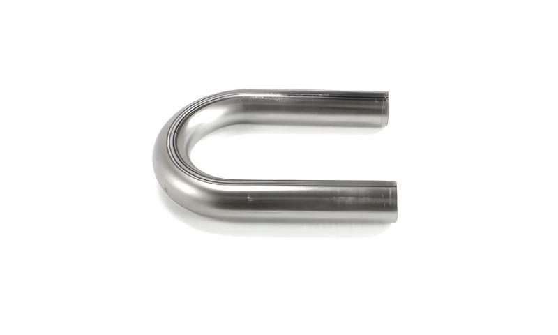
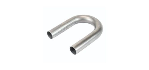
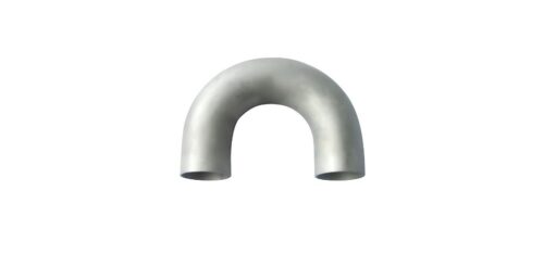
The Buttweld u bends are also critical elements in an industrial network of piping in which fluid flow needs to travel in a reversed direction without affecting the structural integrity. These fittings are largely applicable in heat exchangers, boilers, condensers, offshore platforms and refinery pipelines. The curved geometry ensures that there is a smooth transition of the flow and that the thickness of the walls remains constant at the bend. In high pressure and high temperature settings, dimensional stability and confirmed values of weight have a direct impact on safety and reliability.
In the calculation of engineering, real mass is important. Structural supports, anchors and pipe rack are modeled on the cumulative load of the pipes and fittings. A well-constructed Buttweld U Bend weight Chart assists engineers to make comparatively precise estimates of weight based on nominal size, schedule and radii. This guarantees an improved load distribution and eliminates overloading during installation or overworking over time during use.
Standard Dimensional Reference Table (Schedule 40)
| Nominal Size (Inch) | Outer Diameter (mm) | Bend Radius (mm) | Wall Thickness (mm) | Approx Weight (Kg) |
| 1/2” | 21.34 | 38 | 2.77 | 0.45 |
| 3/4” | 26.67 | 38 | 2.87 | 0.60 |
| 1” | 33.40 | 51 | 3.38 | 0.95 |
| 1 1/2” | 48.30 | 76 | 3.68 | 1.85 |
| 2” | 60.30 | 102 | 3.91 | 2.95 |
| 2 1/2” | 73.00 | 127 | 5.16 | 4.85 |
| 3” | 88.90 | 152 | 5.49 | 6.80 |
| 4” | 114.30 | 203 | 6.02 | 11.50 |
| 5” | 141.30 | 254 | 6.55 | 16.90 |
| 6” | 168.30 | 305 | 7.11 | 22.40 |
The table above gives base values of popular sizes used under Schedule 40. These are some of the values that are normally used in initial design and procurement estimation. Although the weight can differ by a small amount based on the grade of the material used and the tolerance of the manufacturer, these values provide reliable information to use in structural computation.
Dimensional consistency guarantees the seamless alignment of welding and less welding on-site adjustment. By incorporating correct weight information in the piping design, engineers are able to have better support spacing and system balance.
Schedule 80 and 160 Heavy Wall Data
| Nominal Size (Inch) | SCH 80 Thickness (mm) | SCH 80 Weight (Kg) | SCH 160 Thickness (mm) | SCH 160 Weight (Kg) |
| 1” | 4.55 | 1.20 | 6.35 | 1.45 |
| 1 1/2” | 5.08 | 2.40 | 7.14 | 3.05 |
| 2” | 5.54 | 3.60 | 8.74 | 4.40 |
| 3” | 7.62 | 8.10 | 11.13 | 9.75 |
| 4” | 8.56 | 13.80 | 13.49 | 16.20 |
| 5” | 9.53 | 19.50 | 15.88 | 23.80 |
| 6” | 10.97 | 27.90 | 18.26 | 33.50 |
| 8” | 12.70 | 45.60 | 23.01 | 58.40 |
The higher schedules are chosen in case of steam line, petrochemical systems, and heavy process applications when the internal pressure is highly increased. The higher the thickness of the wall, the greater the mass of the fitting, which has direct bearing on the design of supporting and installation planning.
Large diameters need to have noticeable weight variation even with small changes of thickness. To ensure that there is no mechanical instability, engineers have to consider these changes to ensure that the structural supports are not overloaded.
Structural and Performance Highlights
- High mechanical strength suitable for demanding industrial pressure systems.
- Smooth internal curvature that reduces turbulence and pressure drop.
- Reliable weld compatibility for secure and leak-proof joint formation.
- Capability to operate in temperature conditions up to approximately 550°C depending on material grade.
- Uniform wall thickness distribution that enhances long-term durability.
Extended Large Diameter Weight Table
| Nominal Size (Inch) | Outer Diameter (mm) | Bend Radius (mm) | SCH 40 Weight (Kg) | SCH 80 Weight (Kg) |
| 10” | 273.00 | 508 | 55.50 | 68.40 |
| 12” | 323.90 | 610 | 78.90 | 96.20 |
| 14” | 355.60 | 711 | 108.30 | 131.50 |
| 16” | 406.40 | 813 | 145.60 | 176.40 |
| 18” | 457.00 | 914 | 188.50 | 226.80 |
| 20” | 508.00 | 1016 | 236.40 | 283.90 |
| 24” | 609.60 | 1219 | 345.70 | 412.60 |
Buttweld U bends with large diameter are commonly used in transfer lines of refineries, offshore modules, and thermal power plants. The radius of the bends and the volume of the material increase the mass considerably with the increase in the size. That is why proper load calculation is imperative when positioning hangers and designing anchors.
Detailed weight references are used in the fabrication teams to prepare slurries required during the spool preparation and the lifting arrangement planning. Buttweld U Bend Weight Chart is a good tool of engineering to maintain structural balance and operation efficiency.
Manufacturing and Quality Control Overview
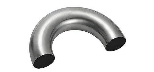
Buttweld U bends are made under carbon steel, stainless steel, alloy steel, duplex steel and nickel-based alloys depending on project requirements. The processes of forming are cold bending of small size and hot induction bending of thicker metal. Post-forming heat treatment assists in removing the remaining stresses and ensures uniformity of dimensions.
The inspection processes take the form of dimensional inspections, wall thickness inspection, surface inspection and hydrostatic testing. Such quality controls guarantee compliance with international piping standards on every element and uniformity of weight of a structure in terms of planning.
Conclusion
Buttweld U bends are also essential parts of industrial piping systems in which strength, dimensional stability, and load stability are of utmost importance. The appropriate estimation of the weight contributes to the sound structural design, load distribution, and planning of the installation. Through reference to a confirmed Buttweld U Bend Weight Chart, the engineers and project planners would be able to ensure the mechanical reliability, optimum use of materials, and long-term systems performance in the harsh industrial conditions.