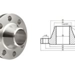
Stainless Steel Weld Neck Flanges Weight Chart: Sizes, Standards, and Technical Insights
February 6, 2026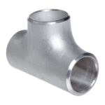
Buttweld Equal Tee Weight Chart – Complete Guide for Easy Reference
February 9, 2026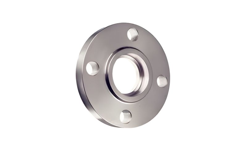
The Stainless Steel Socket Weld Flanges Weight Chart is an important piece of technical information that is applied in the design, installation, and maintenance of piping systems. The socket weld flanges are usually used in high-pressure and high-temperature settings where the strength of the joints and the resistance to leaks are vital. The knowledge of the real or approximate weight of these flanges assists the engineers in planning the structural loads, safe handling, and adhere to the engineering standard.
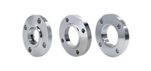
Socket weld flanges have a recessed socket that is used to insert the pipe before welding. This design offers a smooth bore, less turbulence, and ensures a better fatigue resistance. The material of choice is stainless steel, which is highly resistant to corrosion, durable and strong in its mechanical properties making the accuracy of weight particularly significant in the long-term use in industries.
The Cognizance of Socket Weld Flanges in Piping Systems.
Socket weld flanges are those applied in piping systems that have a small diameter and are subject to a high level of pressure and temperature. The pipe is slipped into the flange socket, followed by a strong and compact joint that is formed by fillet weld. Such a connection reduces the leakage risk and increases the structural reliability.
The stainless steel socket weld flanges are produced in different grades of 304, 304 L, 316, and 316L. The density and strength characteristics of each grade vary slightly and in effect,affect the flange weight of the standard weight charts.
Socket Weld Flange Specification
| Size | 1/2″ (15 NB) to 48″ (1200NB) |
| Standards | ANSI B16.5, ANSI B16.47 Series A & B, MSS SP44, ASA, API-605, AWWA, Custom Drawings |
| Pressure Ratings | Class 150, Class 300, Class 400, Class 600, Class 900, Class 1500, Class 2500 | PN6, PN10, PN16, PN25, PN40, PN64 etc. |
| Carbon Steel Socket Weld Flange/ SW Forged Flanges | ASTM A105/A105N, A350 LF1, LF2 CL1/CL2, LF3 CL1/CL2, A694 F42, F46, F48, F50, F52, F56, F60, F65, F70, A516.60, 65, 70 (Spectacle Blind Flange, Spacer Ring/Spade Flange), Steel RST37.2, C22.8 |
| Stainless Steel Socket Weld Flange/ SW Forged Flanges | ASTM A182 F202, F304/304L/304H, F316/316L, F316H, F316TI, F310, F321, F904L |
| Alloy Steel Socket Weld Flange/ SW Forged Flanges | ASTM A182 F1, F5, F9, F11, F22, F91 |
| Special Alloy Socket Weld Flange/ SW Forged Flanges | Duplex, Super Duplex, Nickel Alloys |
| Flange Face Type | Flate Face (FF), Raised Face (RF), Ring Type Joint (RTJ) |
| Coating/Surface Treatment | Anti-rust Paint, Oil Black Paint, Yellow Transparent, Zinc Plated, Cold and Hot Dip Galvanized |
| Value Added Services | CNC Machining, Customised Flanges |
What Is a Stainless Steel Socket Weld flanges weight chart?
Weight chart is a standard table that records flange dimensions and weights and their respective nominal pipe size and pressure class. These charts are drawn in accepted standards and serve as a guide when engineers do their calculations and when planning material.
In the chart, the information normally involves:
- Nominal Pipe Size (NPS)
- Pressure Class
- Outer Thickness and outer diameter.
- Kilograms.
This information enables engineers to have an approximate estimation of the weight of the system and prevent overloading of supports and structures.
Stainless Steel Socket Weld Flanges Weight
| NOMINAL SIZE | DIMENSIONS | WEIGHT (KG) | ||||
| NPS(Inches) | DN (mm) | FLANGEMM | FLANGETHICKNESS | SOWSW | WN | BLIND |
| 1/2 | 15 | 88.9 | 11.2 | 0.4 | 0.5 | 0.4 |
| 3/4 | 20 | 98.6 | 12.7 | 0.6 | 0.7 | 0.6 |
| 1 | 25 | 108 | 14.2 | 0.8 | 1 | 0.9 |
| 1 1/4 | 32 | 117.3 | 15.7 | 1 | 1.3 | 1.2 |
| 1 1/2 | 40 | 127 | 17.5 | 1.3 | 1.7 | 1.5 |
| 2 | 50 | 152.4 | 19.1 | 2.1 | 2.6 | 2.4 |
| 2 1/2 | 65 | 177.8 | 22.4 | 3.3 | 4.1 | 3.9 |
| 3 | 80 | 190.5 | 23.9 | 3.9 | 4.9 | 4.9 |
| 3 1/2 | 90 | 215.9 | 23.9 | 4.8 | 6.1 | 6.2 |
| 4 | 100 | 228.6 | 23.9 | 5.3 | 6.8 | 7.0 |
| 5 | 125 | 254 | 23.9 | 6.1 | 8.6 | 8.6 |
| 6 | 150 | 279.4 | 25.4 | 7.5 | 10.6 | 11.3 |
| 8 | 200 | 342.9 | 28.4 | 12.1 | 17.6 | 19.6 |
| 10 | 250 | 406.4 | 30.2 | 16.5 | 24 | 28.6 |
| 12 | 300 | 482.6 | 31.8 | 26.2 | 36.5 | 43.2 |
| 14 | 350 | 533.4 | 35.1 | 34.6 | 48.4 | 58.1 |
| 16 | 400 | 596.9 | 36.6 | 44.8 | 60.6 | 76.1 |
| 18 | 450 | 635 | 39.6 | 48.9 | 68.3 | 93.7 |
| 20 | 500 | 698.5 | 42.9 | 61.9 | 84.5 | 122.0 |
| 24 | 600 | 812.8 | 47.8 | 86.9 | 115 | 185.0 |
Themodeterminating Factors that influence Socket weld Flange weight.
The weight of the finished stainless steel socket weld flange is subject to a number of technical factors. Knowing these variables would help in the right use of the weight chart.
- Nominal, larger pipe sizes are preferred, since they will increase the material volume.
- The pressure rating, with the higher classes of the one demanding a heavier section.
- Grade and material density of stainless steel.
- Standards of manufacturing tolerance.
- Machining and finishing specification.
- All of these factors cause the differences in the flange weight, even in the same size range.
Real-life applications of weight charts in Engineering.
Weight charts are applied in the real-life scenario to compute the pipe rack loads, lifting needs and transportation planning. Engineers tend to multiply the individual flange weight with the number of flanges used in a system to determine the impact of overall load. This ensures mechanical stability, healthy installation practices and durability of operations.
Weight charts are particularly significant in pressure-sensitive systems whereby improper load distribution may cause joint stress, vibration problems or structural failure.
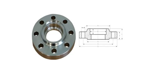
Stainless steel socket weld flanges dimensions
| NPS Of SWRF | (NPS) | 1/2 | 3/4 | 1 | 1 1/4 | 1 1/2 | 2 | 2 1/2 | 3 |
|---|---|---|---|---|---|---|---|---|---|
| Outer Dia | (O) | 90 | 100 | 110 | 115 | 125 | 150 | 180 | 190 |
| Dia of RF | (R) | 34.9 | 42.9 | 50.8 | 63.5 | 73 | 92.1 | 104.8 | 127 |
| Minimum Thickness | (tf) | 9.6 | 11.2 | 12.7 | 14.3 | 15.9 | 17.5 | 20.7 | 22.3 |
| Hub Dia | (X) | 30 | 38 | 49 | 59 | 65 | 78 | 90 | 108 |
| Through Hub Length | (Y) | 14 | 14 | 16 | 19 | 21 | 24 | 27 | 29 |
| Bore Dia | (B1) | 22.2 | 27.7 | 34.5 | 43.2 | 49.5 | 61.9 | 74.6 | 90.7 |
| Socket Depth | (B2) | 15.8 | 20.9 | 26.6 | 35.1 | 40.9 | 52.5 | 62.7 | 77.9 |
| Bolt Circle Dia | (D) | 10 | 11 | 13 | 14 | 16 | 17 | 19 | 21 |
| Bolt Holes Dia | (W) | 60.3 | 69.9 | 79.4 | 88.9 | 98.4 | 120.7 | 139.7 | 152.4 |
| Flanges Bolt Number | (I) | 15.9 | 15.9 | 15.9 | 15.9 | 15.9 | 19.1 | 19.1 | 19.1 |
| Weight KG | (n) | 4 | 4 | 4 | 4 | 4 | 4 | 4 | 4 |

Conclusion
The Stainless Steel Socket Weld Flanges Weight Chart is a necessary engineering tool, which will help in proper system design, safe handling, and effective execution of the projects. Having known the impact of flange size, pressure grade, and material grade on weight, the professionals will be able to make their choices wiser and minimize the risk of expensive mistakes. A safe weight chart can be used when planning, installing or when making maintenance and guarantees accuracy, safety and durability when used in a harsh piping operation.