Complete End Cap Weight Chart for Industrial Pipe Systems
February 6, 2026
Stainless Steel Socket Weld Flanges Weight Chart: Sizes, Pressure Classes, and Usage
February 9, 2026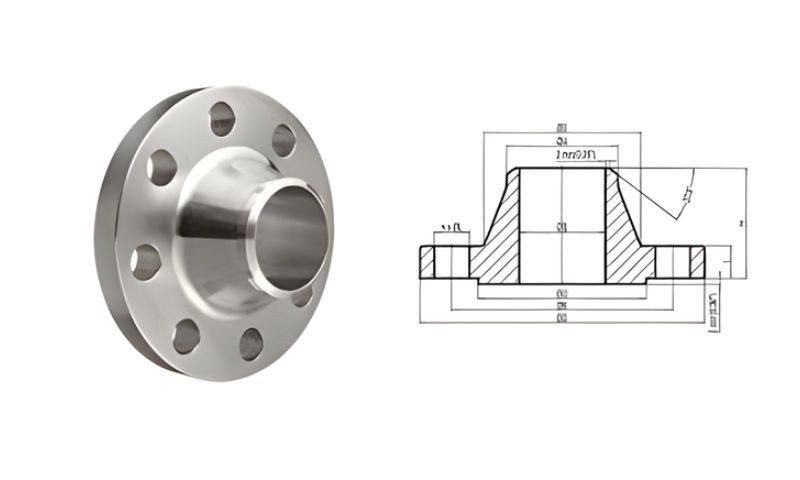
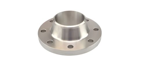
Stainless Steel Weld Neck Flange is commonly applied in high pressure and high temperature piping systems because of its high level of strength and long-term viability. These flanges have a long tapered hub that is welded to the pipe, enabling the stress to be spread out evenly along the joint. A Stainless Steel Weld Neck Flanges Weight Chart is a necessary tool that helps the engineers and the project planners to compute the system loads correctly, design pipe supports, as well as the structural safety on a broad basis.
Adequate flange weight data is important in eliminating overloading of piping supports and other equipment attached to it. Unify the accuracy of the planning and minimize the chance of any mistakes in installing a complicated network of piping systems.

Understanding Stainless Steel Weld Neck Flanges
Weld neck flanges are designed with specific applications in demanding industrial applications with pressure, temperature, and mechanical stress, being a significant issue. They are designed in a unique way to reduce the concentration of stress and increase the longevity of the system.
Weight Chart of Stainless Steel Weld Neck Flanges
| NOMINAL SIZE | DIMENSIONS | WEIGHT (KG) | |||
|---|---|---|---|---|---|
| NPS (Inches) | DN (mm) | FLANGE OD A MM | FLANGE THICKNESS D MM | WN | BLIND |
| 1/2 | 15 | 133.4 | 30.2 | 3.1 | 3.0 |
| 3/4 | 20 | 139.7 | 31.8 | 3.7 | 3.5 |
| 1 | 25 | 158.8 | 35.1 | 5.2 | 5.0 |
| 1 1/4 | 32 | 184.2 | 38.1 | 7.7 | 7.4 |
| 1 1/2 | 40 | 203.2 | 44.5 | 10.9 | 10.4 |
| 2 | 50 | 235 | 50.8 | 16.2 | 15.6 |
| 2 1/2 | 65 | 266.7 | 57.2 | 23.7 | 22.6 |
| 3 | 80 | 304.8 | 66.5 | 36.2 | 34.8 |
| 4 | 100 | 355.6 | 76.2 | 55.3 | 53.9 |
| 5 | 125 | 419.1 | 91.9 | 92.5 | 90.8 |
| 6 | 150 | 482.6 | 108 | 143.0 | 141 |
| 8 | 200 | 552.5 | 127 | 215.0 | 214 |
| 10 | 250 | 673.1 | 165.1 | 406.0 | 411.0 |
| 12 | 300 | 762 | 184.2 | 572.0 | 592.0 |
Design and Construction Characteristics
Weld neck flanges are butt-welded to the pipe, making a smooth and continuous area between the pipe and the flange bore. The design enhances the efficiency of the flow and minimizes turbulence, which are applicable to critical service lines.
Common Stainless Steel Grades Used
- SS 304 for general corrosion resistance
- SS 316 for chemical and marine environments
- SS 304L and SS 316L for improved weldability
Stainless Steel Weld Neck Flanges Grade Weight Chart
| Grade | Density (g/cm³) | Avg Weight per Flange (kg) |
|---|---|---|
| SS 304 | 7.93 | 12.5 |
| SS 304L | 7.90 | 12.3 |
| SS 316 | 7.98 | 12.9 |
| SS 316L | 7.95 | 12.7 |
| SS 321 | 7.92 | 12.4 |
Why Stainless Steel Is Preferred
Stainless steel has great corrosion resistance, mechanical strength and dimensional stability, which guarantees a long service life despite extreme conditions of operation.
Importance of a Stainless Steel Weld Neck Flange Weight Chart
A Stainless Steel Weld Neck Flange Weight Chart is a standardized weight chart using nominal pipe size, pressure class, and standards of dimensional requirements. Such information is mandatory in proper planning and secure installation.
Key Benefits of Using a Weight Chart
- Accurate estimation of total piping system weight
- Proper design of pipe supports and load-bearing structures
- Safer handling during transportation and installation
- Better compliance with engineering drawings and specifications
Reliable weight data improves overall system integrity and operational safety.
Stainless Steel Weld Neck Flanges Size Weight Chart
| Nominal Size (NB) | Inch Size | Approx Weight (kg) |
|---|---|---|
| 15 NB | 1/2″ | 2.5 |
| 25 NB | 1″ | 4.2 |
| 50 NB | 2″ | 7.8 |
| 80 NB | 3″ | 12.5 |
| 100 NB | 4″ | 18.4 |
| 150 NB | 6″ | 29.6 |
| 200 NB | 8″ | 48.5 |
Factors Affecting Weld Neck Flange Weight
The weight of stainless steel weld neck flanges varies depending on several technical parameters that must be evaluated during system design.
Primary Weight-Influencing Parameters
- Nominal Pipe Size (NPS): Larger sizes significantly increase flange weight
- Pressure Class: Higher ratings require thicker material sections
- Material Grade: Alloy composition and density affect overall mass
- Manufacturing Standards: ASME, ANSI, and DIN standards differ in dimensions
Understanding these factors ensures accurate flange selection and load calculations.
Industrial Applications of Stainless Steel Weld Neck Flanges
Due to their strength and fatigue resistance, weld neck flanges are widely used in critical industrial systems.
Stainless Steel Weld Neck Flanges KG Weight Chart
| Size (Inch) | Weight (kg) |
|---|---|
| 1/2″ | 2.5 |
| 1″ | 4.2 |
| 2″ | 7.8 |
| 3″ | 12.5 |
| 4″ | 18.4 |
| 6″ | 29.6 |
| 8″ | 48.5 |
Common Application Areas
- Oil and gas transmission pipelines
- Chemical and petrochemical processing plants
- Power generation and thermal systems
- High-pressure steam and boiler lines
- Offshore and marine piping installations
Advantages of Stainless Steel Weld Neck Flanges
Key Performance Benefits
- Excellent performance under high pressure and temperature
- Reduced stress concentration at the flange joint
- Smooth internal bore for improved flow characteristics
- High resistance to corrosion and oxidation
- Long operational life with minimal maintenance
Stainless Steel Weld Neck Flanges MM Dimension Weight Chart
| OD (mm) | Thickness (mm) | Approx Weight (kg) |
|---|---|---|
| 89 | 12 | 2.5 |
| 108 | 14 | 4.2 |
| 152 | 16 | 7.8 |
| 191 | 18 | 12.5 |
| 229 | 20 | 18.4 |
| 279 | 22 | 29.6 |
| 343 | 24 | 48.5 |
Conclusion
The Stainless Steel Weld Neck Flanges Weight Chart is an essential instrument for obtaining accuracy, safety, and efficiency when piping systems are being designed. Knowing the weight of flanges, material grades, and standard dimensions, industries may perfect the distribution of loads, streamline the process of installations, and provide a long-term rating.